This project was initially published on Tech Master Event for the Master of Espressif contest in January 2026. Unfortunately, it was not selected among the winners. Anyway it was a fun project to make and it’s useful everyday at home!
RollBee turns a traditional roller garage door into a Zigbee-enabled smart device using ESP32-H2, custom PCB, and open-source integration with Zigbee2MQTT and OpenHAB. This project demonstrates how IoT can modernize existing systems without waste. It leverages Espressif’s ESP32-H2 and Zigbee SDK to create a practical IoT solution, showcasing innovation, sustainability, and open-source collaboration – key values of the Master of Espressif contest.
It all started when I broke the last RF key of my garage door. I didn’t want to replace it, I wanted to connect it to my smart home ecosystem. But why replacing the motor controller when it still works? As the motor controller also has a physical switch to operate it, the idea came to “fake” this switch with a bit of electronics.
My smart home ecosystem is built around Zigbee, Zigbee2MQTT and Openhab, so all the building blocks were designating the winner component: the ESP32-H2 and its IEEE 802.15.4 skills.
A bit of retro-engineering
The controller of my roller garage door is more than just a motor controller. It’s in charge of checking the min and max sensors for the motor to stop it when the door is fully opened or closed. It’s also managing the direction of the motor (open or close) as well as the detectors, to avoid closing the door on a human or an object. The roller door can be operated on the press of a push switch, or via the RF control I broke. You can see the controller on the photo below.
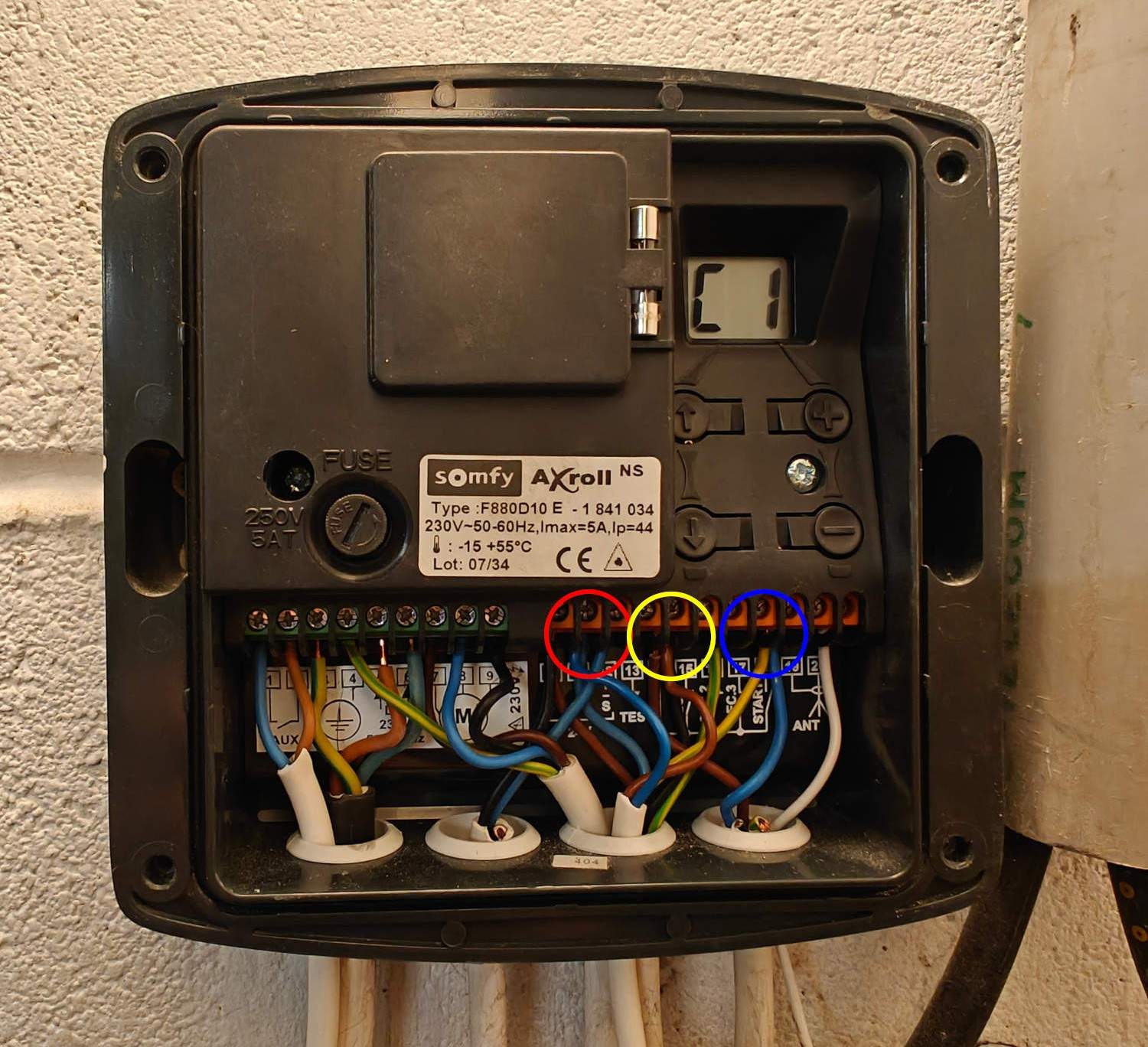
As you see, it’s a Somfy controller. I retro-engineered it and found some ~16V power available between the contacts circled in red and yellow. The physical switch for the open/close operation is connected to the blue-circled contact. Next step is to make an electronics board to control it.
Hardware
Concept
Let’s start from the requirements:
- Power input 16V (let’s say 12-24V)
- “Fake” the physical switch, 12-24V signal
- Basic HMI (few buttons and LEDs)
- Zigbee functionality
- Temperature and humidity sensor (nice to have)
- Open/close sensors (nice to have)
It brings us to the following block diagram:
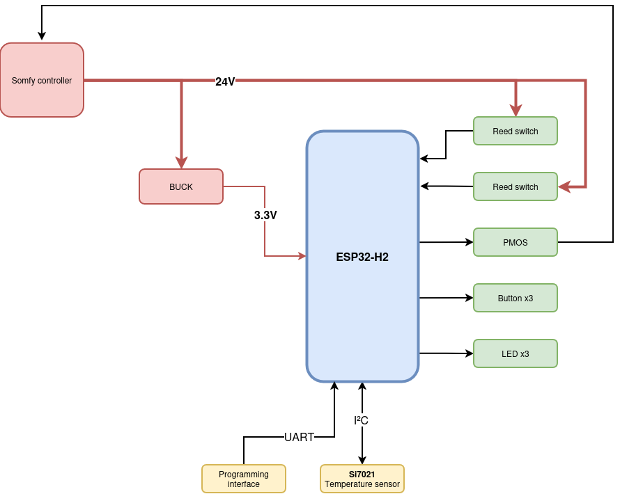
As you can see, the central point is the ESP32-H2. To be exact, it’s an ESP32-H2-WROOM; as a module, I don’t need to design the antenna nor connect an external memory myself. Even better, no QFN device to solder by hand!
The ESP32 needs 3.3V power, when we have 12 to 24V. Then, the solution is a Buck converter. Controlling the Somfy controller as if there was a physical switch will be handled by a PMOS, controlled by the microcontroller. I added an Si7021 temperature and humidity sensor over I²C to the ESP32. The basic HMI is made by 3 push buttons; I added 3 LEDs as well.
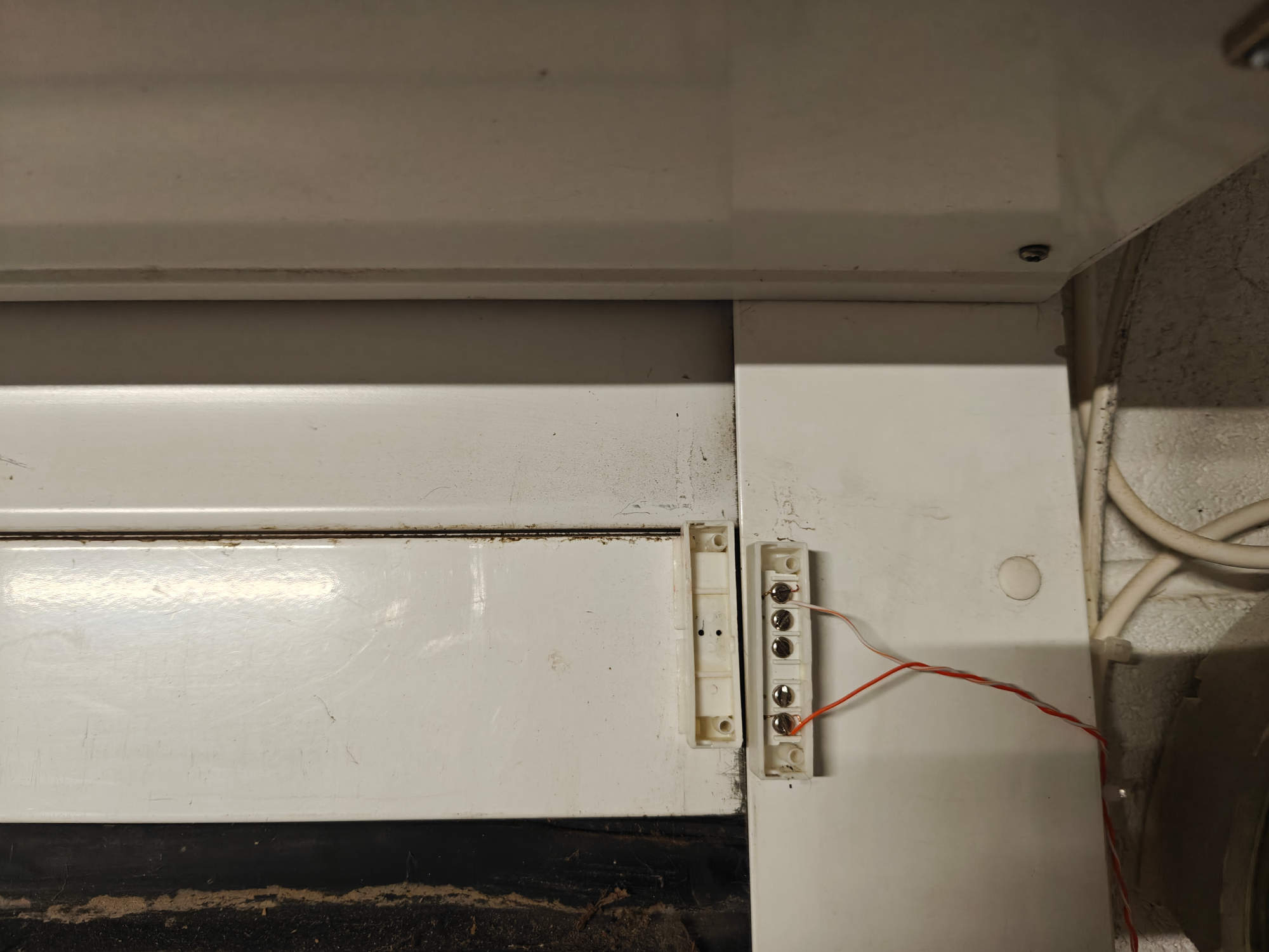
Finally, the open/close sensors are reed switches. A reed switch is composed of a small metal piece, that closes the electrical contact when it’s close to a magnet. I’ve put the reed switch on the roller door frame and the magnet on the moving part, as you can see below.
Schematics
I translated this concept to the following schematics using KiCad, on Linux.
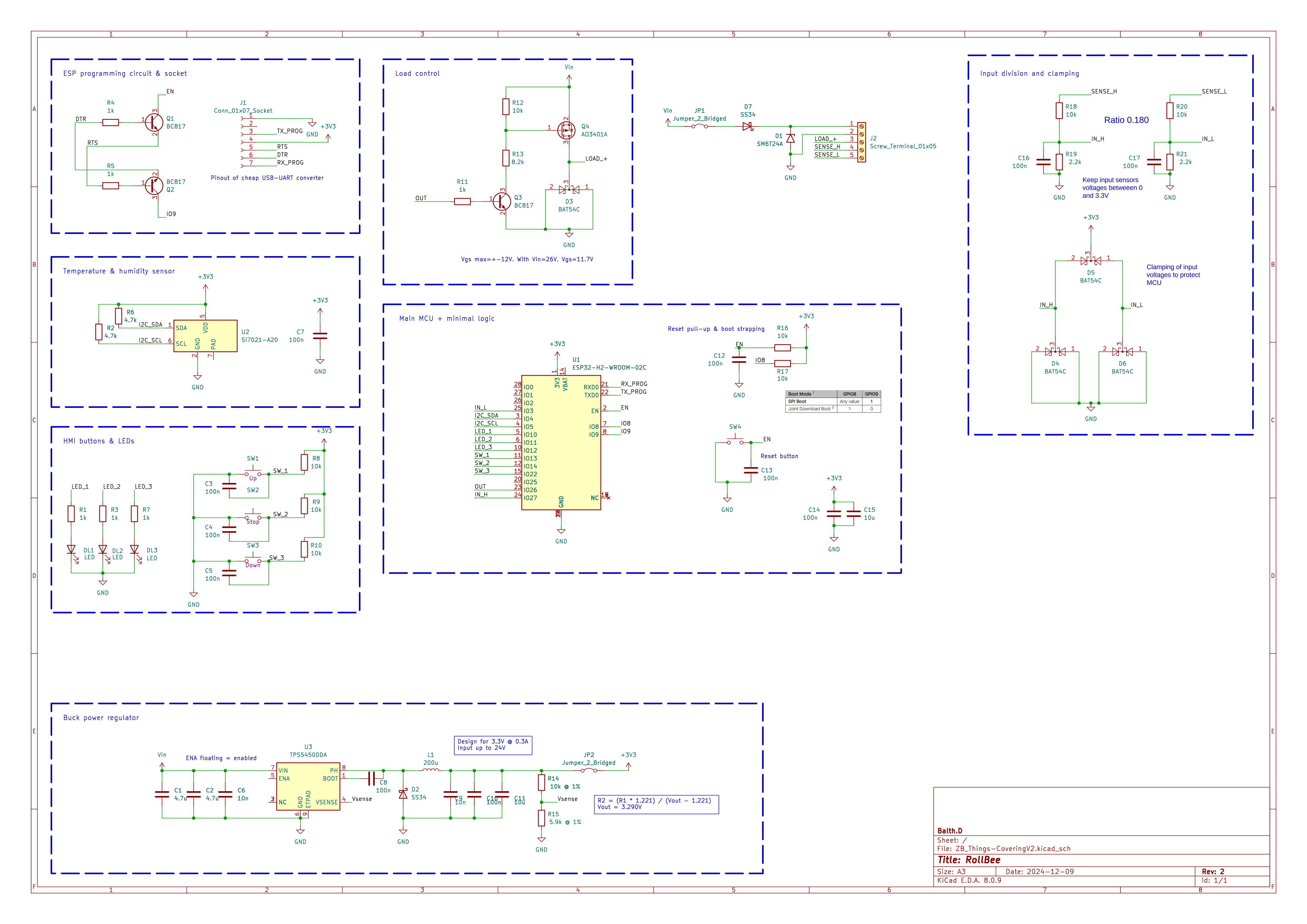
As you can see, I translated each functional block to an an actual electronic block. The inputs from the reed switches are divided to produce 3.3V maximum (the input it again the 12-24V range) and clamped with diodes to make sure that the ESP32 stays safe.
The control of the “load” (the fake physical switch) is made by the PMOS and its control circuit around.
I added a programming circuit around the ESP32 (top left of the schematics) to be able to program it with a standard UART interface.
On the bottom part of the schematics, there is the Buck DC-DC power converter, based on the TPS5450 from Texas Instruments.
The PCB
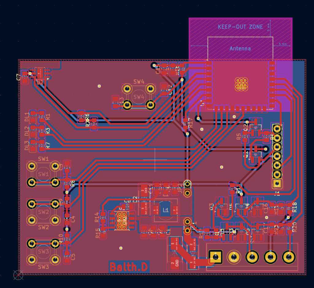
It’s time to make a PCB of it! Again with KiCad, I designed a board with two layers of copper: ground and 3.3V on the bottom, signals on the top. Below is the virtual result.
To make the PCB come live, I’m lucky to have a PCB milling machine. I used it to make the board you can see below. Of course milling is not the last step, I soldered all the components by hand. It was not difficult because the capacitors and resistors I chose are 0805 size. The ESP32 module has castellated holes on the sides, nothing below the component.
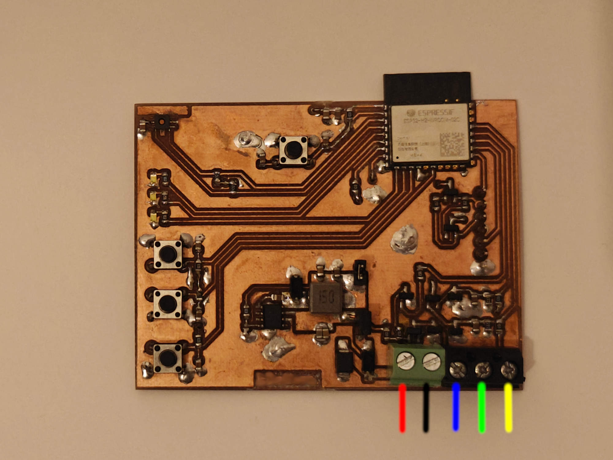
On the red line, the +12-24V has to be connected. Black is the ground, blue the control signal of the physical switch (it will be grounded by the PMOS to trigger the opening/closing). Yellow and green are the negative side of the open/close reed switches; the other side is connected to the +12-24V. When the reed switch is closed, the ESP32 will read a HIGH signal on the corresponding GPIO.
On top we can’t miss the magnificent ESP32-H2-WROOM, with the antenna off the PCB area to avoid perturbating its signal.
Software
ESP32 basics
I had experience with making Zigbee devices, but not really on the ESP32-H2. The best and easiest way to work with such a microcontroller (when you have experience of course) is to use the ESP IDF, by Espressif themselves. It has a Zigbee add-on.
The ESP IDF provides all the drivers to control the ESP32 (GPIOs, buses, protocols, radio…), while the Zigbee add-on provides the Zigbee protocol stack.
All my code is available publicly on the gitHub repository.
The ESP IDF relies strongly on FreeRTOS, a Real Time Operating System. It comes with a full set of functionalities which I used, such as thread, queues and timers.
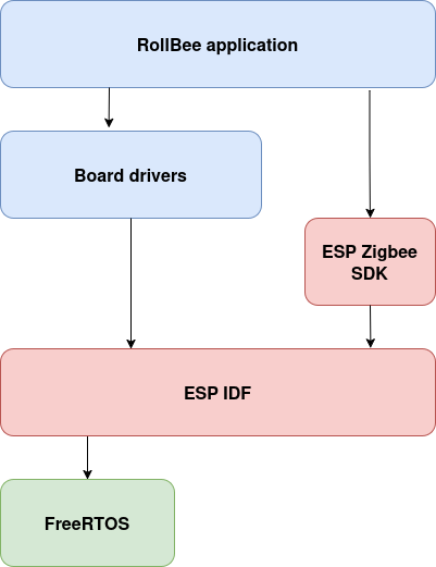
I split my software on two levels, as shown on the following diagram. The base blocks (provided by Espressif) are the IDF and Zigbee SDK as described above. I built my board drivers on top of the IDF and the application itself on top of the board drivers and the Zigbee SDK.
Zigbee model
The Zigbee specification defines a physical device by different ways: the endpoint(s) represents the kind of conceptual devices the board handles (i.e. a light, a sensor…). Then an endpoint contains clusters, that we can see as group of similar data points or controls (such as on/off control, temperature). Then come the attributes, which are the actual data points (like on/off state, temperature measurement, minimal temperature). There are also commands that are actual requests from the controller to the end device.
My device is two things at the same time: a covering device (the closest device type to a roller garage door in the Zigbee specification) and a sensor. It’s then logic that I expose two endpoints.
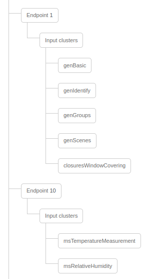
Endpoint 1 (the main one) is a window covering device, handling the minimum mandatory Zigbee clusters and the covering cluster. Endpoint 10 is a temperature sensor device, on which I’ve put the temperature and humidity measurement clusters.
The temperature and humidity values are updated each 4 seconds from the sensor to the Zigbee attributes.
The covering device state (opened, closed or unknown) is updated each time the reed sensors status changes. When the roller-door is not opened -0%- nor closed -100%- (we can’t know where), its state is set to 50%.
If you look at the code structure of my repository, you’ll see that the main.cpp file does the bridge between the BoardXxx.cpp files and the AppZigbee.cpp module. Communication between the Zigbee and the main process is handled by two queues (one for each direction).
When an input changes (reed switch, push button, sensor), the main sends a packet into the queue, then the Zigbee process can handle the change asynchronously. It’s important to never block the Zigbee thread. On the other hand, when the Zigbee stack receives an open/close command from the controller, it notifies the main with another queue. The main thread can then process the command.
My code is a mix of C and C++. I’m more in favor of Object Oriented Programming, but FreeRTOS, ESP-IDF and the Zigbee SDK are really C-oriented, so it’s sometimes difficult to apply OOP concepts.
Zigbee2MQTT and OpenHAB
As you read previously, a Zigbee device is connected to a central controller. In the Zigbee world, the central controller (or hub) is almost always made by the manufacturer of the devices and you can’t use devices from another manufacturer with such hub.
This limitation is removed with the open-source project Zigbee2MQTT. I used Zigbee2MQTT as the controller of my Zigbee network. This is a powerful project because you can extend it with the devices you want. The RollBee is supported, with the proper custom converter which is available on my repository.
The name is self-explaining, Zigbee2MQTT takes the Zigbee devices and bridges the input and output clusters to an MQTT server. Now that the data from the device is available, it has to be integrated in a smart home ecosystem.
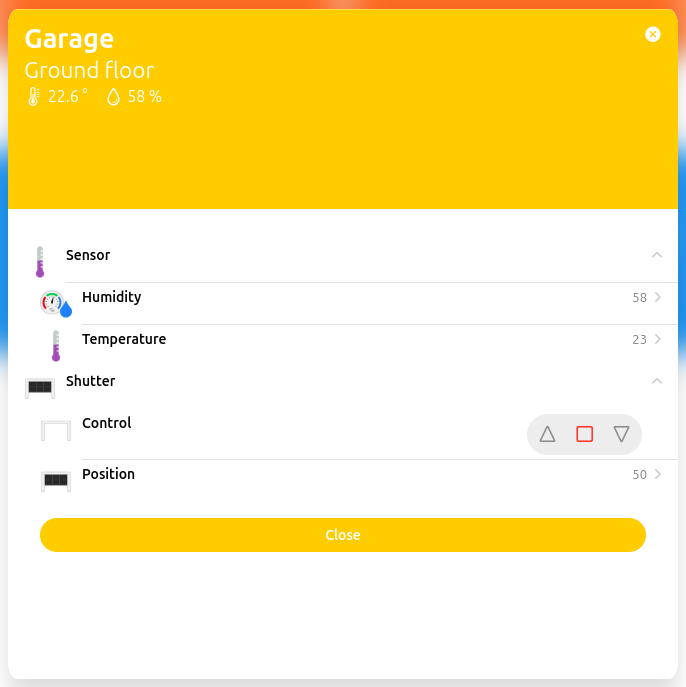
I use OpenHAB to connect to the MQTT thing (a thing is a protocol in the OpenHAB vocabulary) to the MQTT server and interact with the RollBee features exposed by Zigbee2MQTT. The right items and I’m now able to control the RollBee from the OpenHAB application on my phone and computer!
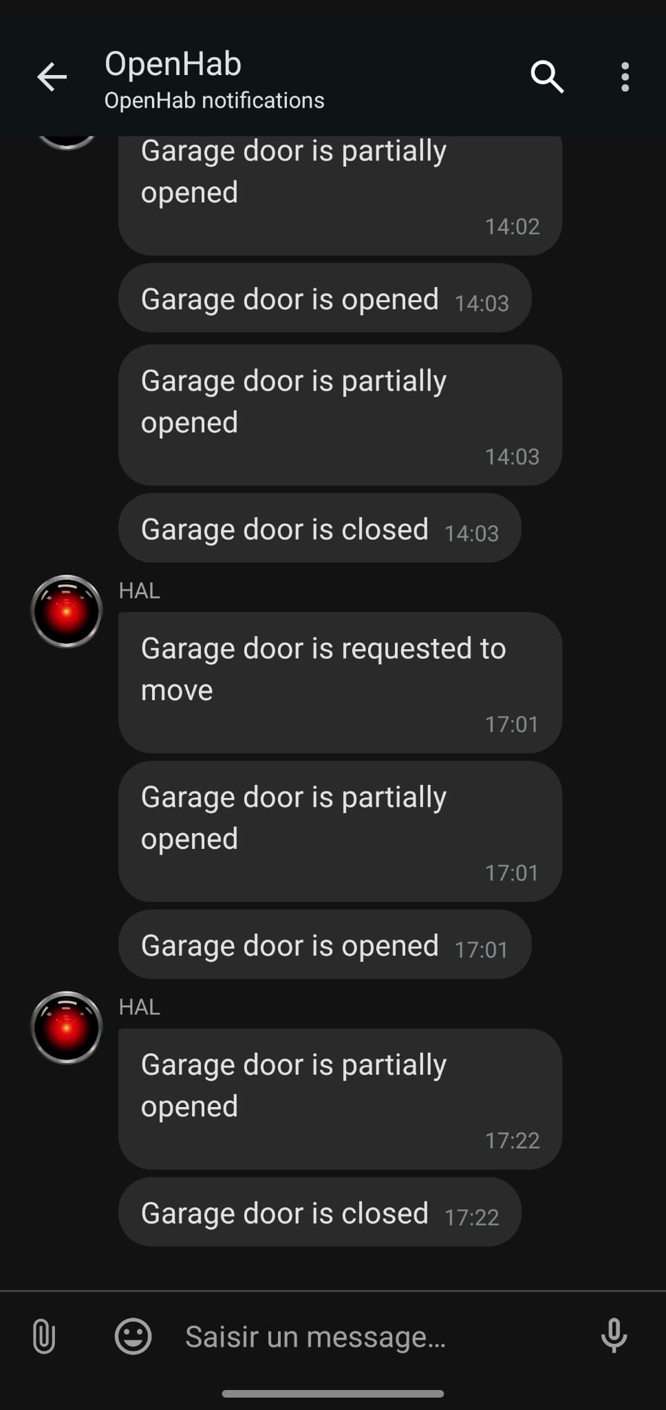
OpenHab is scriptable too. I then made a rule that sends me a notification each time the door is moving.
Conclusion
I think my project is a good example of how to make life easier with IoT. More than that, I brought a basic garage door to the 2020’s without changing its controller: no waste. Of course this is not something that is technically easy to do. But I had fun doing it and I think that it proves that replacing everything each time a technology changes is not mandatory.
The hardware and software I made are well separated in blocks, that will be easy to reuse them in the future. I plan to use this project as the foundation of some more Zigbee devices I plan to make.
Working with the ESP32-H2 was a huge strength from many points of view. On the hardware side, it is a big time and complexity saver to have a WROOM module taking in charge all the RF design and the memory. For the software, Espressif comes with a very strong SDK (the IDF) for basic and advanced usecases such as Zigbee. My code started with the examples provided on the Espressif GitHub repositories and the strong online documentation available.
Of course there can always be more: why not adding the Matter smart-home protocol support? Why not supporting HomeAssistant in addition of OpenHAB? Adding OTA updates would be a huge plus, as the device will stay in my garage, I don’t want to remove the device each time I add a feature… Maybe for the next step, stay tuned!
![]()